
TSTN-057
Calibration Screen#
Abstract
This technote describes the Simonyi Calibration Screen, including its design, installation, alignment, and performance requirements.
Overview#
The Simonyi Calibration Screen is used to reflect light into the camera to produce flat-field calibration images for the Rubin Observatory telescope.
The screen is illuminated by a projector located at the center of the screen assembly. Light from the projector is first reflected by the Calibration Reflector (tstn-049) and then directed onto the calibration screen. The telescope collects light from the ~10m wide illuminated screen to generate flat-field images used in camera calibration.
The screen is mounted on the rotating portion of the dome at an azimuth of 233.8 degrees. When the dome is parked, the TMA can point at it with an AZ of -126.2 degrees and Elevation of 23 degrees.
The overall diameter of the screen assembly is 10.27 m. The reflective portion of the screen spans radii from 4.18 m to 9.27 m. Blackened regions surrounding the reflective section (3.18–4.18 m and 9.27–10.27 m) reduce scattered light.
The screen can rotate between two configurations: * Operational position: inclined 23 degrees from vertical and aligned with the telescope optical axis. * Service position: vertical orientation to allow maintenance access. In the service position, sufficient clearance exists between the screen and the dome wall to allow a platform lift to access the projector optics and illumination sources located at the center of the screen. The screen is expected to remain in the operational configuration for the vast majority of telescope operations.
The interface between the Calibration Screen and the dome structure is defined in LTS-126.
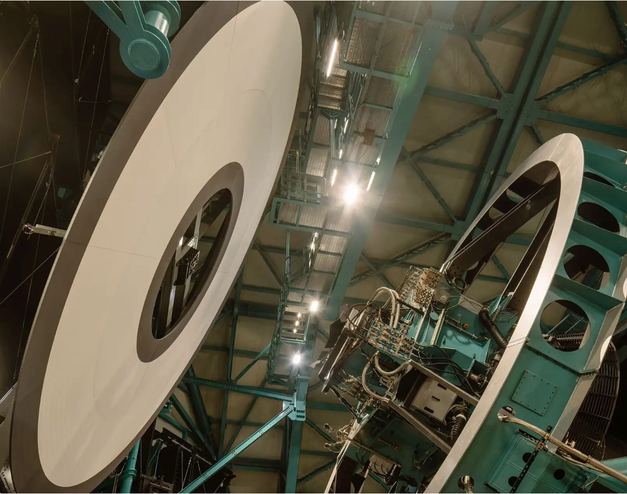
Fig. 1 Calibration screen, aligned with the TMA.#
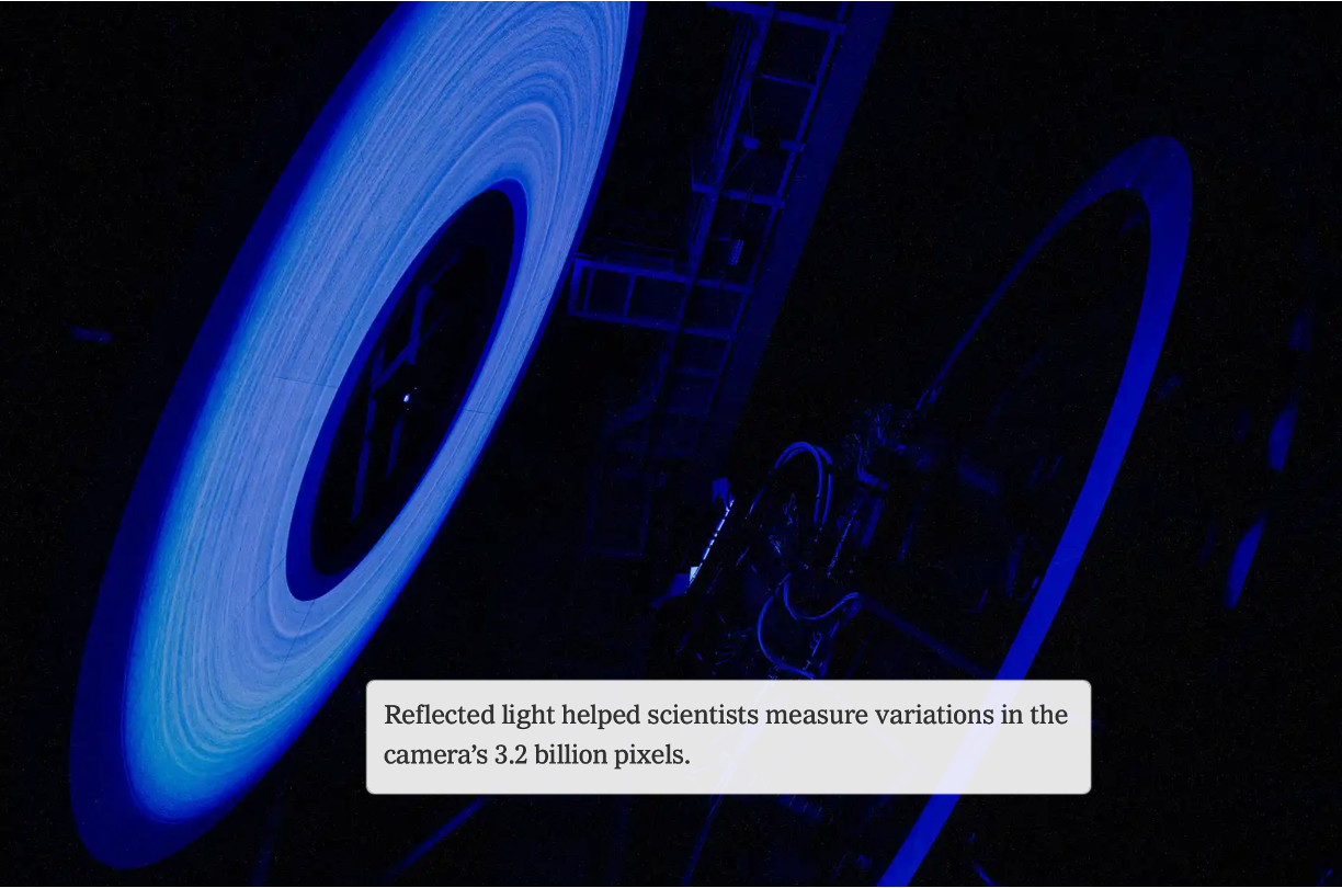
Fig. 2 Calibration screen, illuminated. Published in NYTimes.#
Design documentation and testing results from LabSphere are available in Docushare Collection-15387.
System requirements#
The calibration screen was designed to achieve optical and mechanical requirements necessary to produce high-quality flat-field calibration images.
Flatness Requirement: The RMS flatness of the calibration screen, measured across the entire reflective optical surface area, shall not exceed 3 mm when the screen is in the operational inclined position.
- Reflectance Requirement:
The reflective coating applied to the screen panels shall provide a hemispherical reflectance greater than 90% across the operational wavelength range.
Blackened regions surrounding the reflective surface shall have reflectance below 6% in order to suppress scattered light.
Panel Alignment: The gap between adjacent screen panels shall not exceed 1 mm.
Telescope Alignment: The calibration screen system shall include alignment reference features that allow the telescope laser tracker system to determine the position of the screen relative to the telescope optical axis.
Mechanical Design#
The calibration screen assembly consists of three primary subsystems:
Steel support structure
Aluminum screen structure
Reflective panels
Steel Support Structure#
The steel support structure mounts the calibration screen to the dome and supports associated instrumentation. The structure consists of two large steel columns attached to the dome. In addition to supporting the calibration screen assembly, the structure also carries the platforms for the Collimated Beam Projector (CBP) and the Laser enclosure.
The original structure was designed by EIE. Fabrication was later completed in Coquimbo by Rovial after steel components were sourced from Switzerland and the United States.
During design review it was determined that the initial structure did not adequately support the Collimated Beam Projector (CBP). A structural stress analysis was therefore performed and additional support brackets were added.
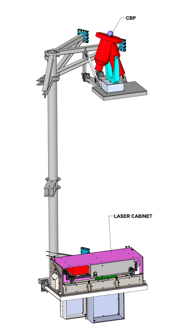
Fig. 3 CBP and Laser enclosure mounted on one of two steel columns.#
Aluminum Screen Structure#
The aluminum support structure for the calibration screen was designed and fabricated by EIE.
The structure is assembled from multiple nearly identical aluminum segments that form the circular frame supporting the panels. The structure rotates about two pivot points and is driven by a motorized actuator that moves the screen between the service and operational positions.
Prior to shipment to Chile, the structure was fully assembled in Italy to verify dimensional accuracy.
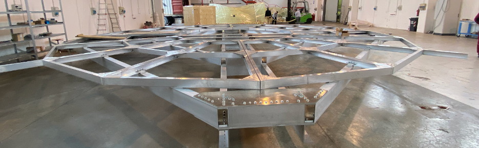
Fig. 4 Aluminum structure assembled in Italy prior to shipment.#
Screen Panels#
The screen surface is composed of 24 individual panels:
16 outer panels
8 inner panels
These panels were constructed under the guidance of EIE and shipped directly to LabSphere. The panels are constructed with an aluminum frame, covered with some kind of canvas (would like to find what this material is). The panels were coated by LabSphere using Permaflect coatings:
Permaflect 94% for the reflective region
Permaflect 5% for absorptive regions
LabSphere measurements indicate:
Reflectance greater than 90% for reflective panels
Absorptive coating reflectance below 5.7%
Less than 3% RMS variation across panels
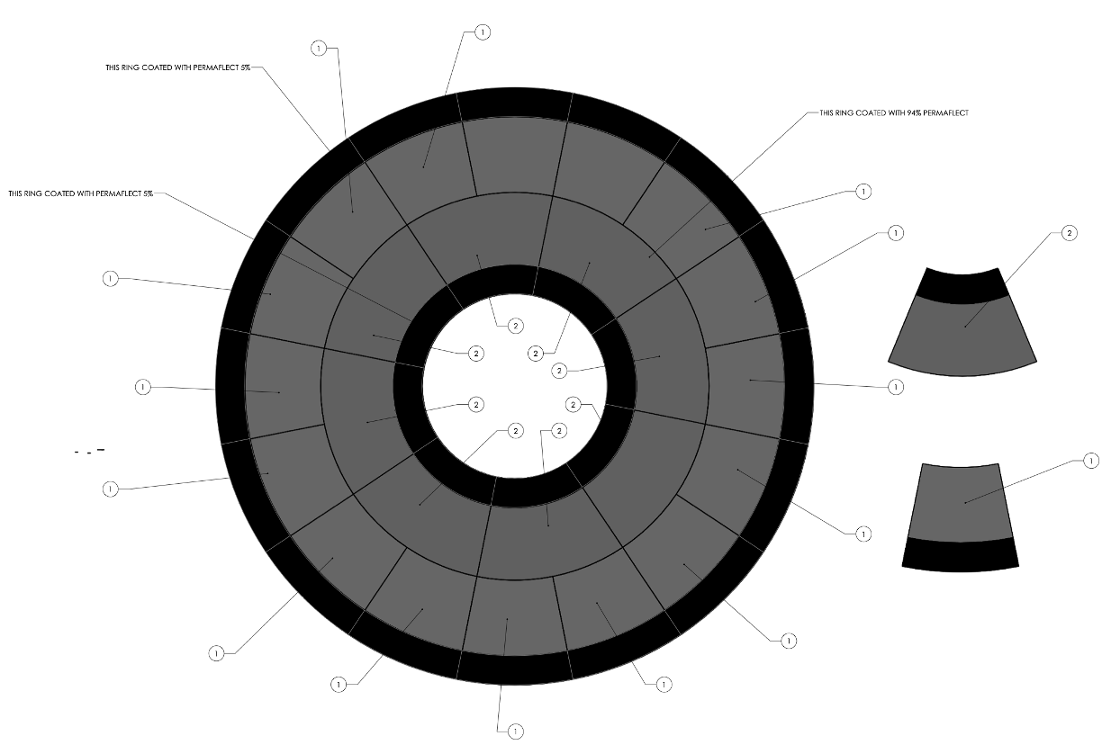
Fig. 5 Drawing from LabSphere on the panels.#
Each panel attaches to the aluminum structure at four locations using adjustable mounting hardware. These adjustment points allow fine control of panel flatness during installation.
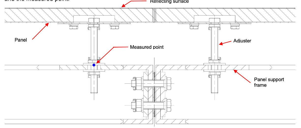
Fig. 6 Mechanism for adjusting each panel for flatness.#
Actuation System#
The calibration screen is designed to rotate between service (vertical) and operational (inclined 23 degrees from vertical) configurations using a mechanical actuator system.
The actuator responsible for this motion has not yet been installed.
Assembly and Installation#
The aluminum structure was shipped to Chile and assembled outside. The mounting holes for the panels were measured using a laser tracker to within specification. The structure was tarped, waiting for installation.
The steel structure was then installed on the dome. When that was installed and its location confirmed, the aluminum structure was brought in through the slit. The aluminum structure was placed in a lifting fixuture, which was then raised with a large external crane. The aluminum structure was lowered into the dome and set on the 8th floor. Since the overhead crane could not reach over to the screen location, the aluminum structure was lifted with mounts on the ceiling.
With the aluminum structure in place, the panels were installed. This was accomplished by lifting the panels by their adjusters on the back, then slid into place and secured from the back.
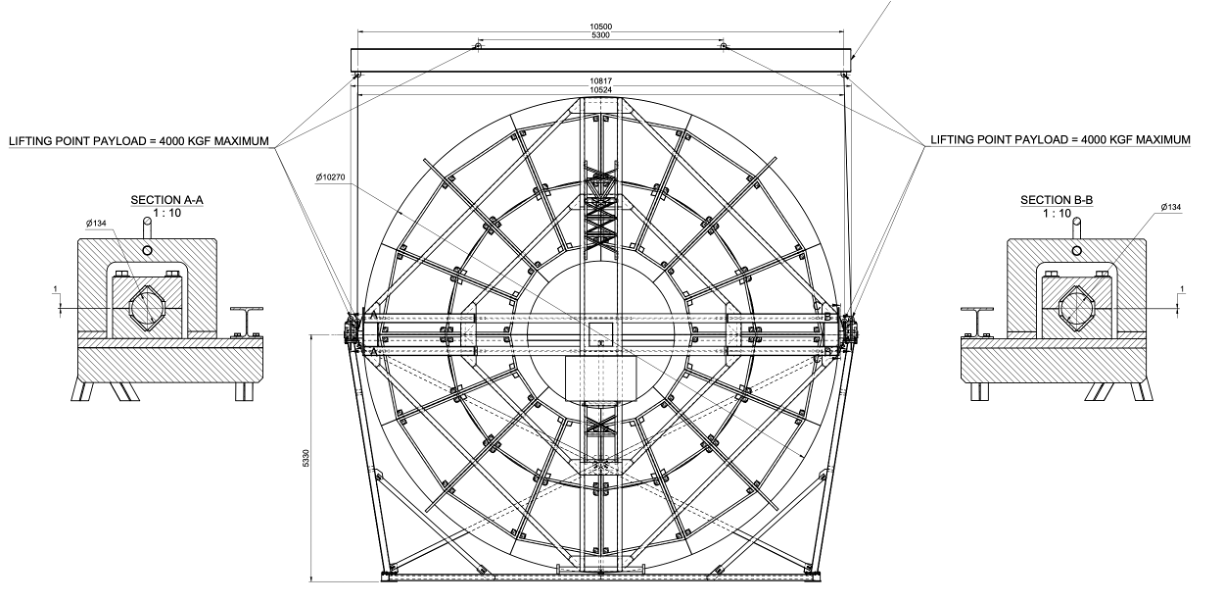
Fig. 7 Aluminum structure drawing, including the lifting fixture. EIE-DWG-46820000A.#
One all panels were installed, they flatness of the screen was measured, which was done using a Leica laser tracker (not the one installed on the TMA). An operator placed an SMR against the screen at each panel adjustment location. After measurements were collected, several panels were adjusted until the surface met the 3 mm RMS flatness requirement.
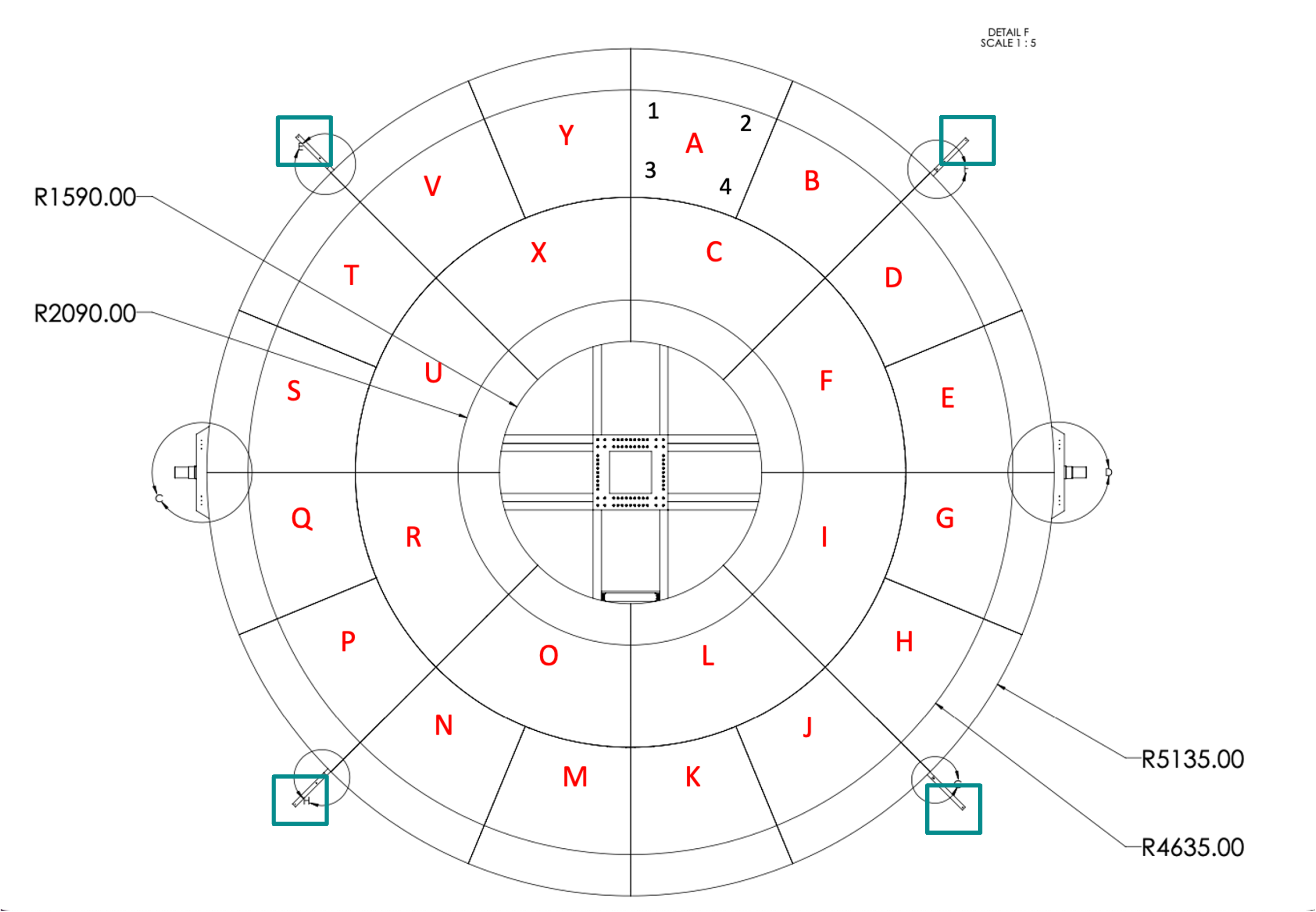
Fig. 8 Numbering of the panels used to measure the flatness of the screen. In the four green boxes are the locations of the SMRs, which jut out from the screen so they can be seen by the Laser Tracker. The numbers identify each of the adjusters on the backside of the panels.#
Alignment#
Because the calibration illumination system is optically fast, accurate alignment between the telescope and calibration screen is required. The standard dome positioning system does not provide sufficient precision for this alignment.
To overcome this limitation, the laser tracker used for daily telescope optical alignment is also used to measure reference retroreflectors mounted on the dome structure. These measurements provide an accurate determination of the relative position between the telescope and dome.
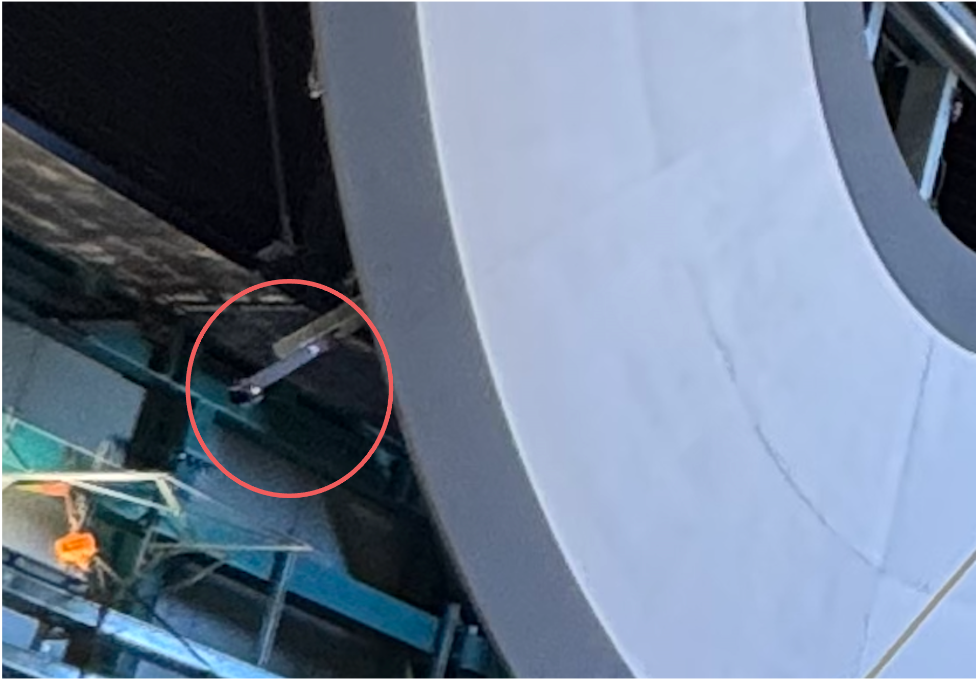
Fig. 9 Picture of one of the SMRs attached to the calibration screen.#
The laser tracker mounted at the center of the TMA cannot directly view the calibration screen. Instead, the aluminum structure includes four radial extensions where spherical mounted retroreflectors (SMRs) are installed. The original extensions were found to be too short to allow reliable visibility from the tracker location, so additional extension pieces were added and SMRs mounted at their ends.
The screen must be approximately aligned before the laser tracker can acquire and lock onto the four SMRs. Once these measurements are obtained, the TMA is moved to achieve the required alignment between the telescope optical axis and the calibration screen.
Laser Tracker Software#
In order to measure the exact location of the calibration screen, the laser tracker is used. This requires use of the Spatial Analyzer software, which can be accessed via remote desktop at lasertracker-vm.cp.lsst.org.
A program was written by Spatial Analyzer that allows us to send commands to it through our scripts. In this case, we use the lasertracker/align.py script with the target “CALIBRATION_SCREEN”.